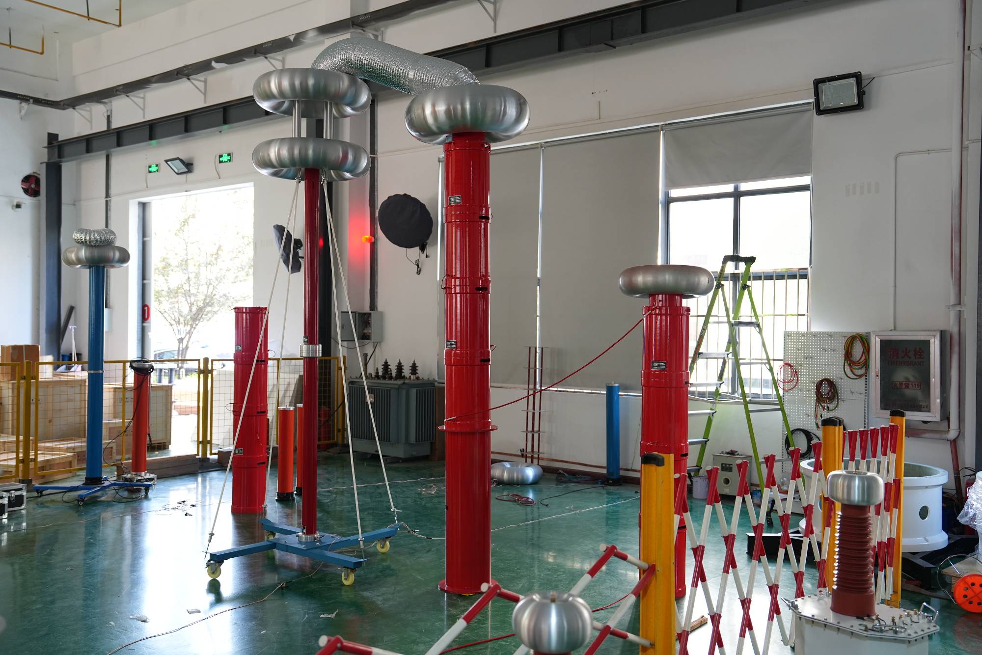
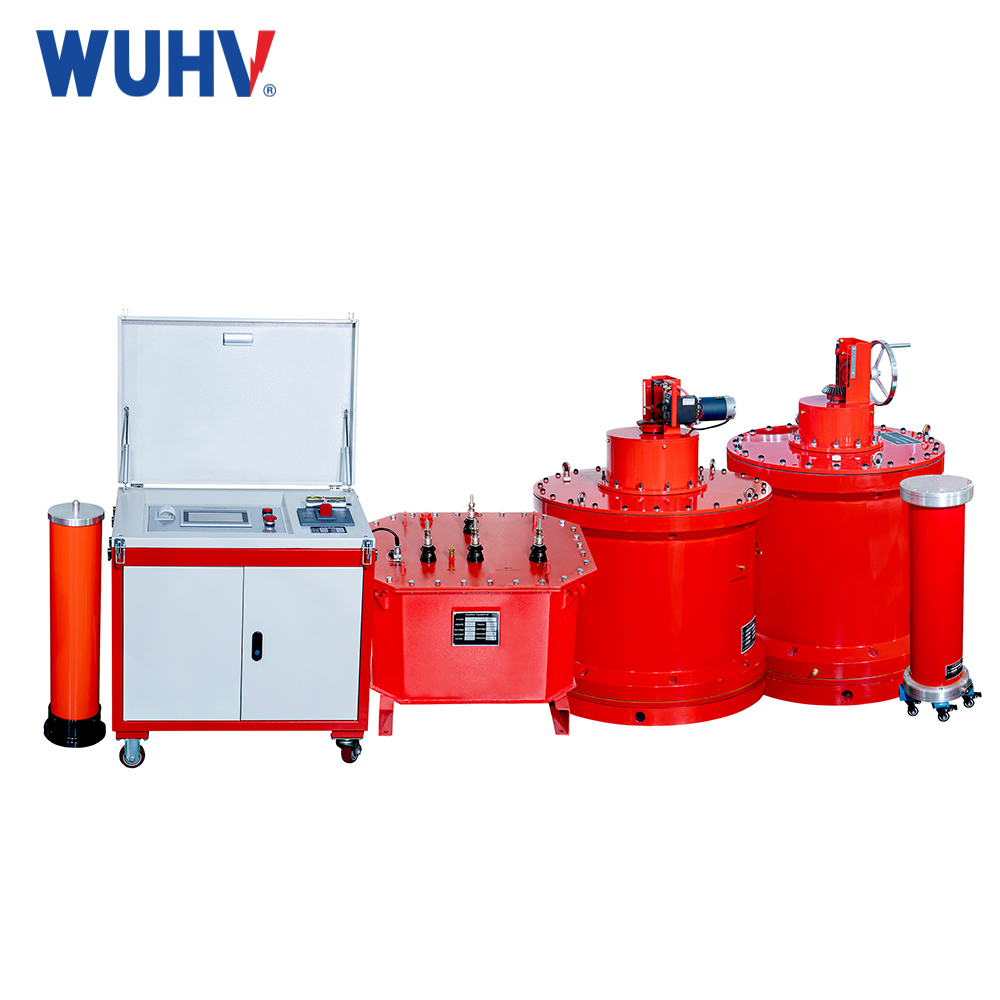
Wuhan UHV specializes in producing series resonance (also known as series resonance test device). Next, we will share with you a brief analysis of the series resonance test device reactor.
Information about reactors: The reason for the low power factor on the input side of the frequency converter is significantly different from the low operating power factor of the power frequency motor. Series resonance is a rational load for electric motors, where the phase of the operating current lags behind the voltage, and the fluctuation of the power factor depends on the phase relationship between the current and voltage. The low power factor of the frequency converter is due to its circuit structure. Variable frequency drives typically have a "AC-DC-AC" structure, where a three-phase AC power source is converted to DC through a three-phase rectifier bridge and filtering capacitor, and then converted to frequency adjustable AC power through a control circuit and inverter tube. In the rectification process, only when the instantaneous value of the AC power supply is greater than the DC voltage UD, the rectifier diode will conduct, and there will be charging current in the rectifier bridge. Obviously, the charging current always appears in a finite time near the peak of the power supply, showing a discontinuous pulse waveform. This non sinusoidal wave has strong high-order harmonic components. The instantaneous power of high-order harmonics is partially '+' and partially 'one', which belongs to reactive power. This reactive power results in a lower power factor of the variable frequency speed regulation system, approximately 0.7-0.75.
Due to the low power factor on the input side of the frequency converter. It is not the current waveform that lags behind the voltage, but rather the high-order harmonic current, so parallel compensation capacitors cannot be used to improve power factor And efforts should be made to reduce high-order harmonic currents, specifically by connecting reactors. JT is a DC reactor connected between the rectifier bridge and the filtering capacitor. The use of one of them has a significant effect, and the combined use of the two can improve the power factor to above 0/95. DC reactors not only improve power factor. It can also constrain the charging surge current at the moment of power connection. Other than that, it is not allowed to connect capacitors in parallel at the output end of the frequency converter, which is the connection end with the motor.
Because the so-called sine wave output by the frequency converter is actually a pulse width modulated wave with pulse width and duty cycle spread according to the sine law. This pulse sequence is composed of alternating conduction of the inverter tube in the frequency converter. If a capacitor is connected to the output end, the inverter tube not only needs to provide current to the motor during the alternating conduction process, but also increases the charging and discharging current of the capacitor, which can cause damage to the inverter tube.
Reactors are not standard equipment for most frequency converters, they are optional accessories. It should be selected according to the needs. Sometimes, in order to reduce the cost of equipment investment, AC reactors are not connected, and the variable frequency speed regulation system is tolerated to operate at low power factors


