
Product List
문의하기
이메일:qiao@hvtest.cc
모바일: +8615871365102
앱은 무엇입니까: +8615871365102
-
What are the main types of motor performance testing
2026-07-30Motor performance testing is an indispensable part of the process of motor research and development, production, and operation. It aims to comprehensively evaluate the electrical performance of the motor under various working conditions, ensuring that the motor can meet design requirements and operate stably.Motor performance testing mainly includes the measurement of electrical parameters such as resistance, insulation resistance, inductance, back electromotive force, Hall effect, load, no-load, friction torque, cogging torque, etc. These parameters directly reflect the health status and electrical characteristics of the motor winding. By measuring these parameters, potential issues such as winding short circuits, open circuits, or insulation aging can be detected in a timely manner, ensuring the safe operation of the motor. At the same time, load performance testing is also an important part of electrical performance testing. It evaluates the output power, efficiency, and temperature
더 -

Testing methods for motor performance
2026-07-30Electric motors are common electric equipment in modern industry, and it is necessary to conduct motor testing to ensure their normal operation.Firstly, one of the most common motor testing methods is insulation testing. It can be conducted through methods such as insulation resistance testing, insulation resistance polarization index testing, dielectric loss testing, etc.Secondly, the winding test of the motor. Winding testing can evaluate the state of a motor by measuring parameters such as resistance, insulation resistance, and mutual inductance of the winding. At the same time, the insulation performance of the winding can also be tested through high-voltage testing to ensure the safety and reliability of the motor under high voltage.In addition, load testing of the motor is also essential. Load testing can evaluate the load capacity and performance of a motor by measuring parameters such as current, power, and efficiency. When conducting load testing, it is necessary to select app
더 -
Functions of DC motor test bench equipment
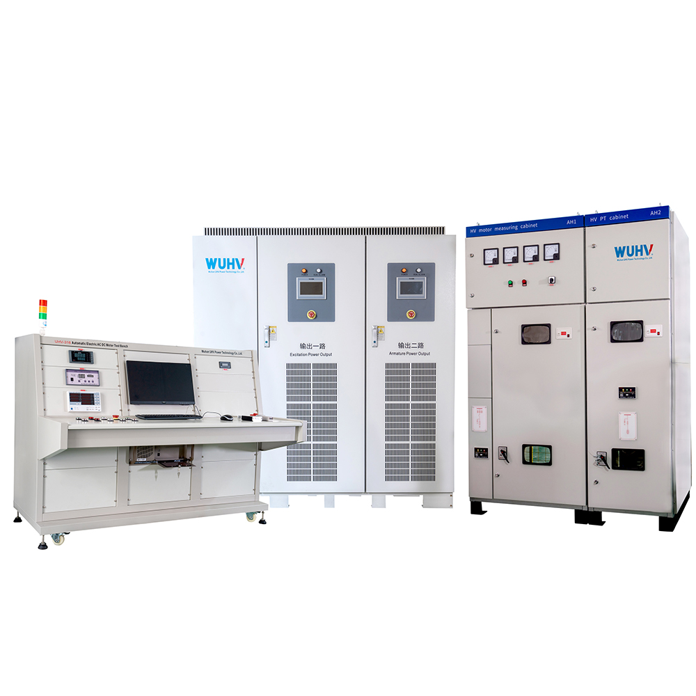
2026-07-29The DC motor test bench equipment is an indispensable testing tool in the motor industry, which can comprehensively test and evaluate the performance of DC motors. The following is a detailed introduction to the DC motor test bench equipment:1、 Main functionsThe DC motor test bench equipment is mainly used to test various performance indicators of DC motors, including motor speed, torque, efficiency, temperature rise, etc. Through these tests, it can be ensured that the performance of the motor meets the design requirements, improving the reliability and service life of the motor.2、 Application scenariosThe DC motor test bench equipment is widely used in motor manufacturers, research institutions, and university laboratories. During the motor production process, testing the motor on a test bench can promptly identify and address potential quality issues, thereby improving product quality. At the same time, research institutions and university laboratories can also use test benches to c
더 -
What is a DC motor test bench
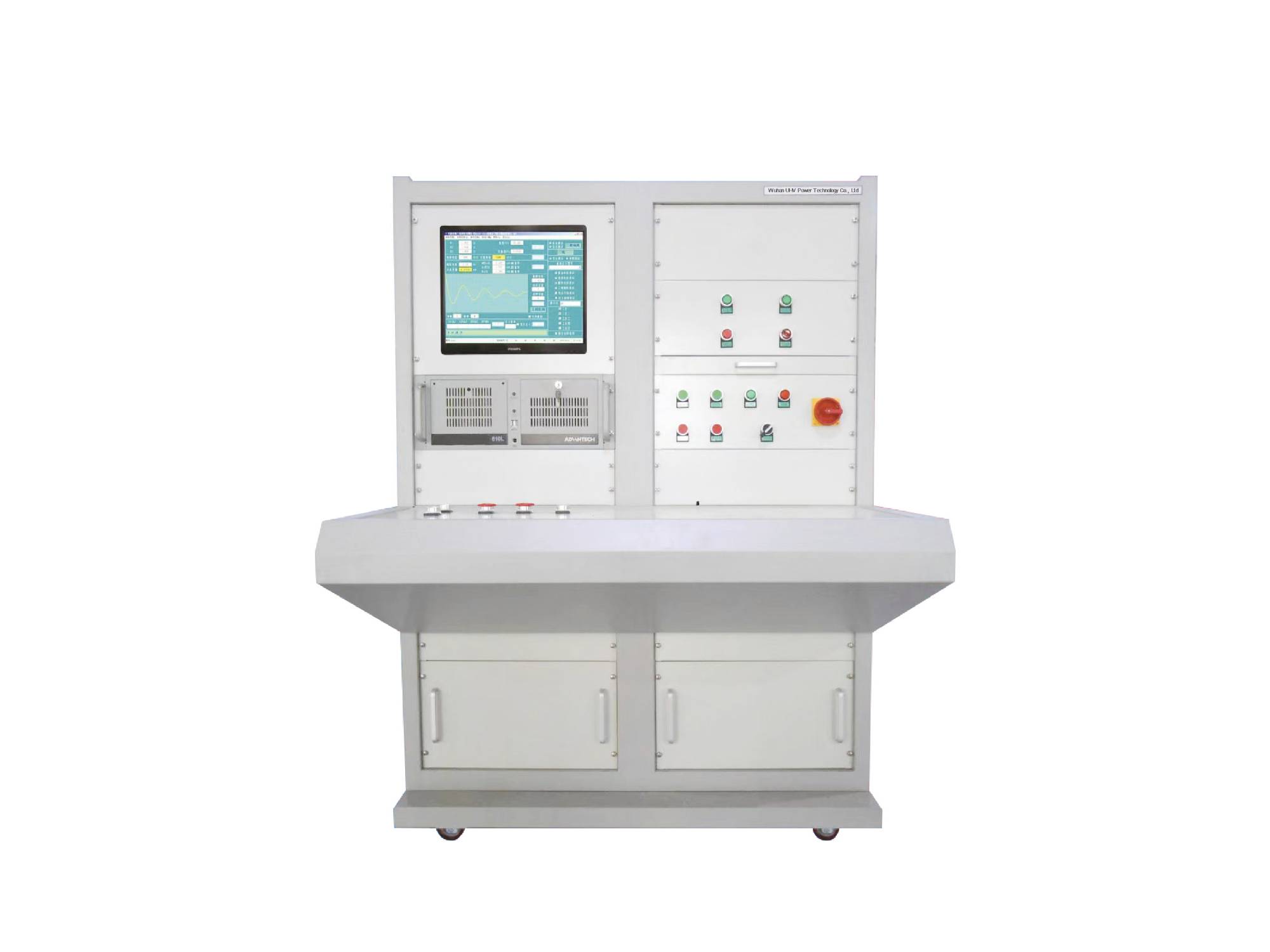
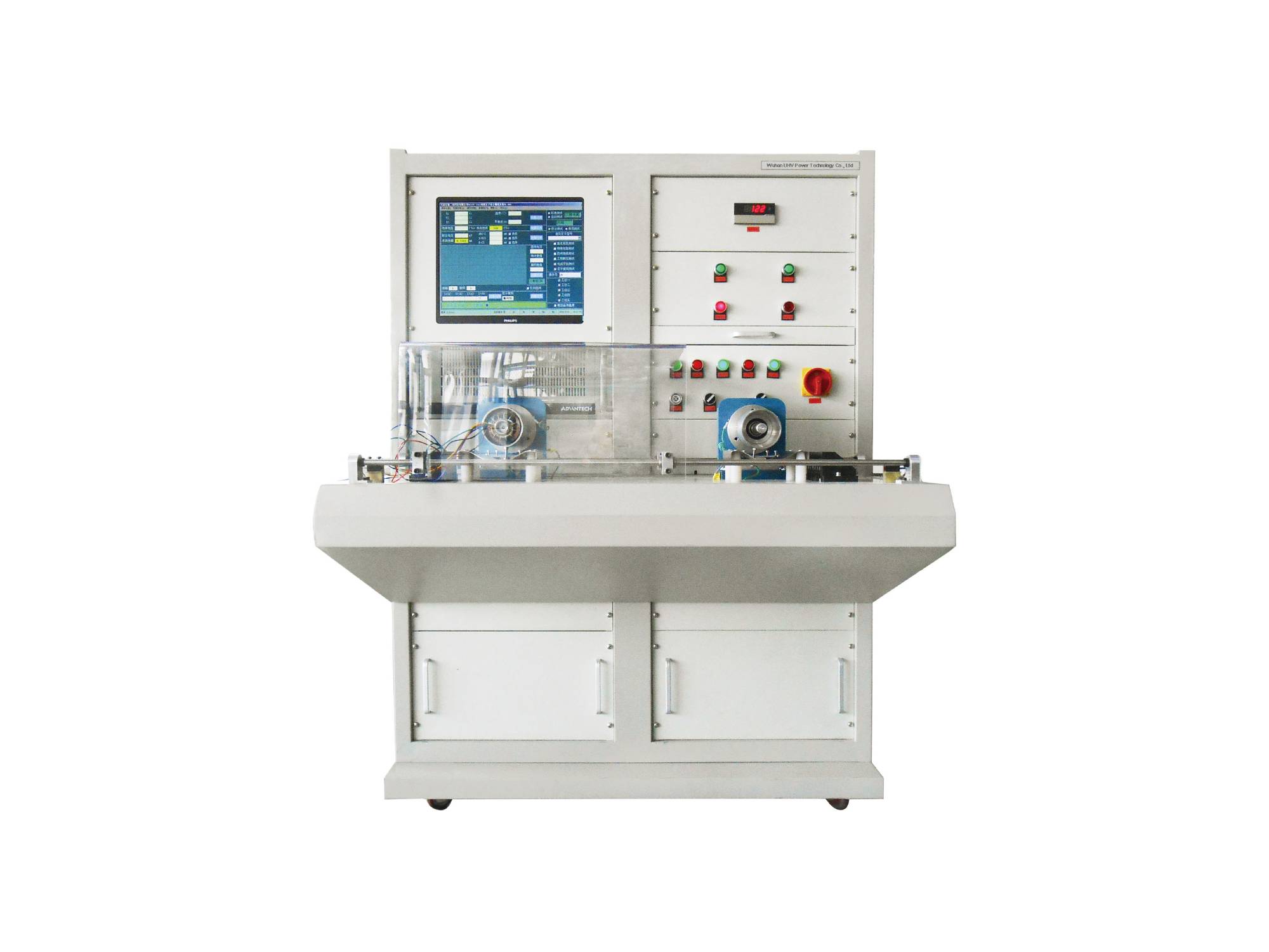
2026-07-29The DC motor test bench is a device used to test and evaluate the performance of DC motors. It is mainly used to measure and inspect whether the motor has faults or damages during operation, as well as to determine its performance. The DC motor test bench usually consists of the following parts:Force measurement system: This is the core part of the entire system, including sensors, weighing devices, and transmission mechanisms, used to measure the output torque and load conditions of the motor.Control system: As the nerve center and control center of the system, including control cabinets and computers, responsible for the control and data acquisition of the entire experimental process.Display recording system: used for recording, storing, and analyzing test data and results.Function and purpose of DC motor test benchThe DC motor test bench can test various parameters of the motor, including voltage, current, input power, output torque, speed, output power, efficiency, temperature, vib
더 -

The Importance of Motor Stator Testing
2026-07-27As an important component of the motor, the stator's performance directly affects the overall performance of the motor. Therefore, conducting stator testing is a crucial step in ensuring the quality of the motor.1、 The Importance of Motor Stator TestingMotor stator testing is an indispensable part of the motor production process. By testing the stator, potential issues can be identified and addressed in a timely manner, ensuring the performance and stability of the motor. At the same time, stator testing also helps to evaluate the lifespan and reliability of the motor, providing important basis for the optimization design of the motor.2、 Common testing methods for motor stator1. Insulation test: Insulation test is to check the insulation performance between the stator winding and the iron core of the motor. By measuring the insulation resistance with a megohmmeter, the insulation status of the stator winding can be determined, thereby ensuring the safe operation of the motor.2. Vol
더 -
What are the types and characteristics of motor testing platforms?
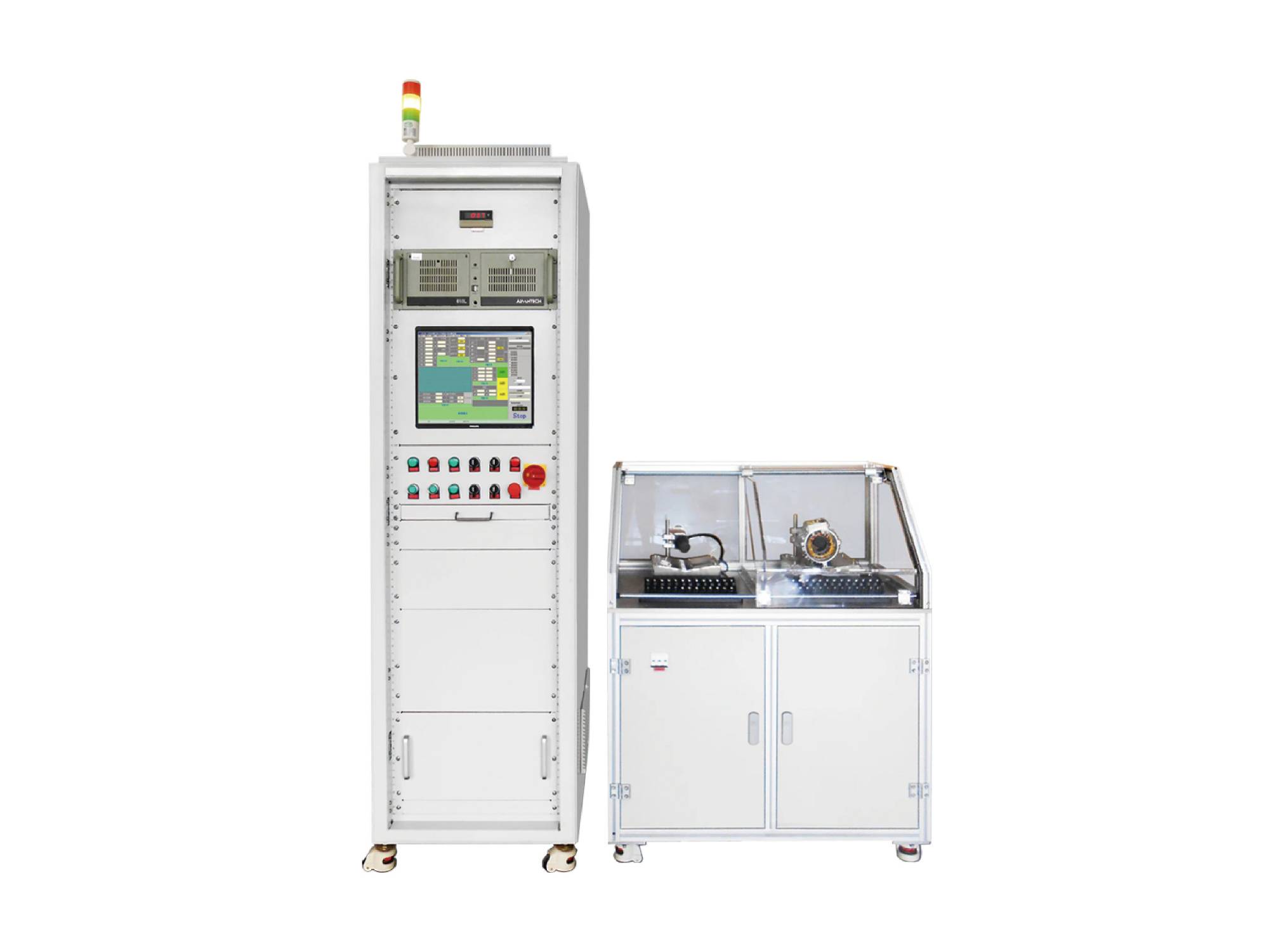
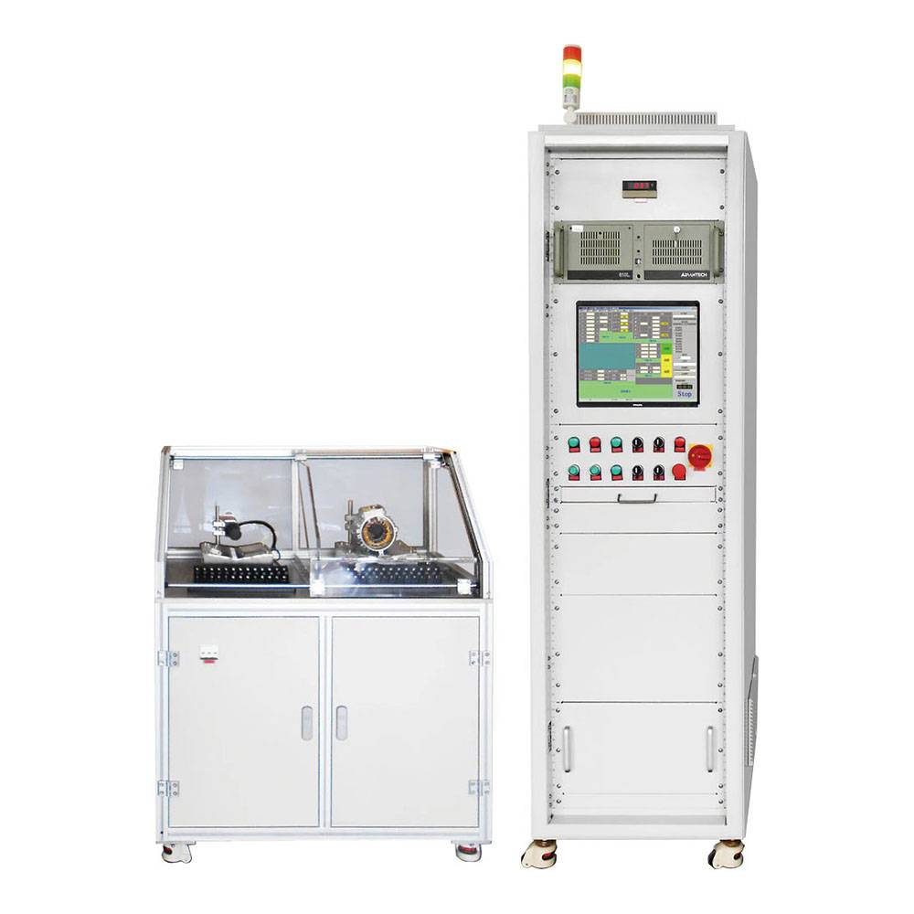
2026-07-27As an indispensable equipment in modern industry, the motor testing platform has a wide variety of types with unique features, aiming to meet the testing needs of different types of motors. From basic electrical performance testing to complex environmental adaptability verification, the motor testing platform provides strong support for the research and development, production, maintenance, and optimization of motors.Main types and their characteristics1、 Intelligent motor comprehensive testing platformThe intelligent motor comprehensive testing platform is a leader in motor testing platforms. It integrates advanced testing technology and automation control methods, and can complete multiple testing tasks. Taking the intelligent motor comprehensive testing platform as an example, this platform is suitable for various tests of AC motors, DC motors, and variable frequency motors after factory and maintenance. It includes multiple components such as industrial computers, test power system
더 -
What is the stator of a motor?
2026-07-27As one of the core components of a motor, the performance and quality of the stator directly affect the stability and service life of the motor. Therefore, strict inspection of the motor stator is a key step to ensure the normal operation of the motor. This article will provide a detailed introduction to the process flow of motor stator detection to ensure the reliability and safety of the motor.Firstly, visual inspection is the first step in the testing process. This step mainly checks whether there is any damage, cracks, deformation or other obvious defects on the surface of the stator. Through visual inspection and necessary measurement tools, potential issues that may affect motor performance can be promptly identified and eliminated.Next is the insulation resistance test. Insulation resistance is an important indicator for evaluating the insulation performance of motor stator. By using an insulation resistance meter, the insulation resistance value of the stator winding to ground
더 -
What are the common models of motor test benches?
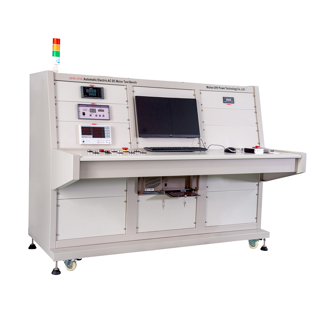
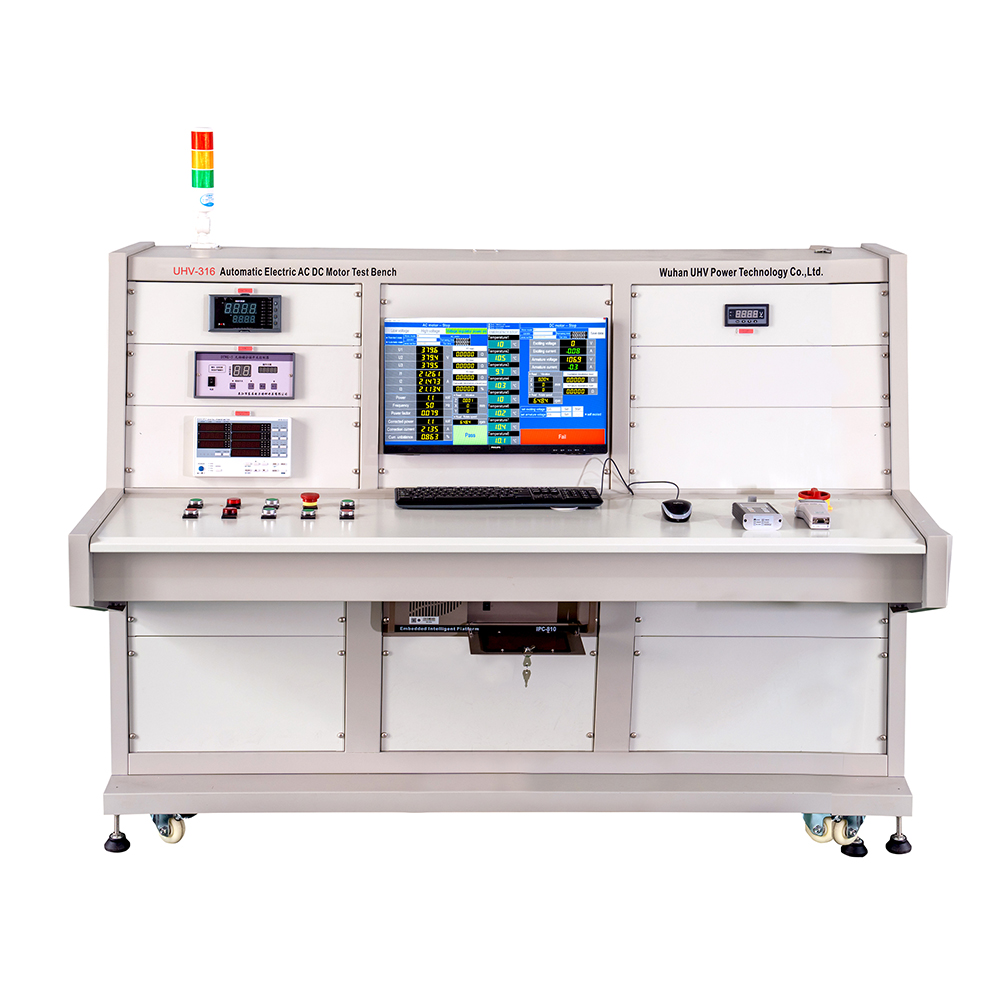
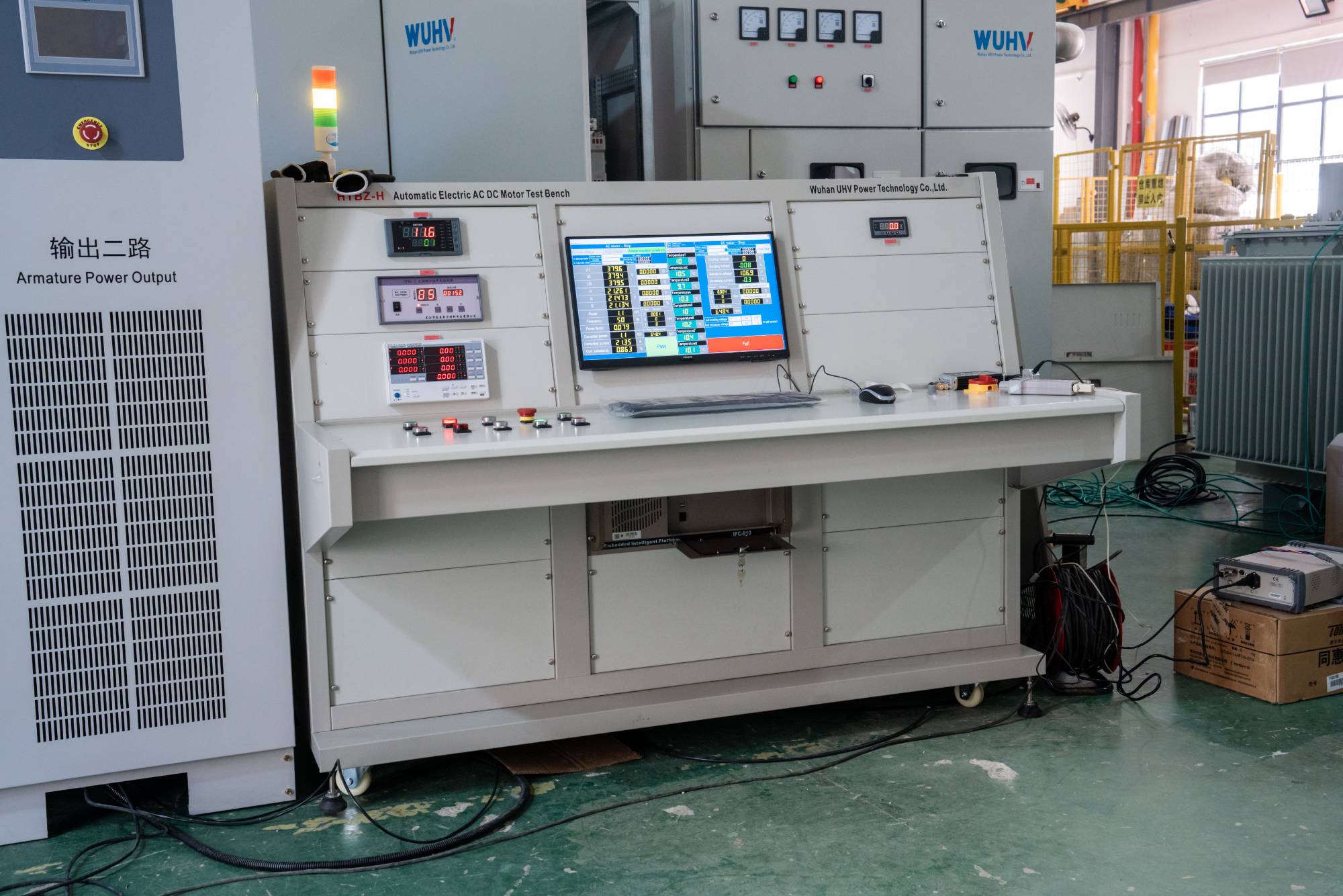
2026-07-27There are various common model names for motor test benches, each with different specifications and functions. Below are a few common model names, let's take a look together.1. Motor test benchThe motor test bench is a universal testing equipment that can test various types of motors, including AC motors, DC motors, low-voltage motors, high-voltage motors, etc; The motor test bench can also test the open circuit voltage, short-circuit current, winding resistance, speed, torque, power, efficiency and other performance parameters of the motor. It can provide detailed performance reports for motor manufacturers and offer users the best motor selection plan.2. Motor testing platformMotor testing bench is a testing equipment with performance testing as its main function, mainly used to test various forms of AC and DC motors; The motor testing platform mainly tests various parameters of motor operation, such as voltage, current, power, speed, efficiency, as well as mechanical and insulat
더 -
What are the common types of motor testing systems?
2026-07-24Motor testing system refers to a set of equipment and methods used for performance testing and evaluation of motors. This system measures and analyzes parameters such as voltage, current, speed, power, and temperature of the motor to determine its performance, efficiency, load capacity, reliability, and potential faults. The motor testing system is widely used in fields such as motor manufacturing, maintenance, and scientific research.According to the type and application scenario of the motor, common types of motor testing systems include the following:1、 DC motor testing systemThe DC motor testing system is mainly used for comprehensive testing of the performance of DC motors. The system has the function of regulating the voltage and current of the DC power supply to simulate the operation status of the motor under different load conditions. In addition, the system can accurately measure parameters such as motor speed, torque, and efficiency.2、 AC motor testing systemThe AC motor tes
더 -
What is the difference between a motor stator testing system and a motor testing system?
2026-07-24Although both the motor stator testing system and the motor testing system are equipment used for motor testing, there are some differences in their testing objects, testing content, testing methods, testing accuracy, and testing costs1. Test object: The motor stator testing system is mainly used to test the stator part of the motor, including the electrical parameters and insulation strength of the stator coil; The motor testing system can be used to test various parts of the motor, including the rotor, stator, winding, bearings, gears, etc.2. Test content: The motor stator testing system mainly tests the insulation resistance, dielectric loss factor, capacitance value, inductance value, insulation strength, leakage current and other electrical parameters of the stator; The motor testing system can test various aspects of the motor, such as electrical parameters, mechanical parameters, power parameters, efficiency parameters, etc.3. Testing method: The motor stator testing system usua
더 -
Which motor tests is the motor testing platform suitable for
2026-07-22The motor testing platform is an important tool for testing and evaluating motor performance, widely used in various types of motor testing projects. It can not only provide test data, but also achieve real-time monitoring and data analysis of the testing process through advanced software services, providing strong support for motor design, optimization, quality control, and fault diagnosis. This article will provide a detailed introduction to which motors the motor testing platform is suitable for, as well as its main testing items and functions.The motor testing platform is widely used for testing various types of motors, including AC motors, DC motors, and stepper motors. AC motor is a common type of motor in industry, widely used in various mechanical equipment. DC motors have been widely used in situations where speed and torque control is required due to their excellent speed regulation performance and starting characteristics. Stepper motors play an important role in automation
더 -
How to measure the quality of the motor stator?
2026-07-22Measure the insulation resistance of the stator coil to ground with a shaking table. If it is greater than 1 megohm, it indicates that the motor stator is in good condition. Measure the insulation resistance between the stator coils, and if it is greater than 1 megohm, it also indicates that there is no problem with the motor stator. Power on test run, measure whether the three-phase current is balanced, and if it is balanced, the motor stator is good.For factories and laboratories, there are professional motor stator measurement equipment. For example, the stator measurement system for AC motors can measure AC withstand voltage, insulation resistance, turn to turn withstand voltage, DC resistance, inductance, reverse embedding, steering, etc. It has ultra-high performance, is compatible with multiple projects, easy to maintain, supports intelligent self inspection, remote fault diagnosis, and online software upgrades. The plug-in design is convenient for disassembly and replacement, a
더 -
Function and purpose of motor test bench
2026-07-22The motor test bench can be used to check motor current, voltage, torque, speed, temperature, etc. It adopts bus feedback type variable frequency feedback loading, and does not pollute the power grid during energy feedback. Can ensure that the electric energy absorbed by the loading motor is fed back to the driving motor. The loader has a constant torque operation function and can fully meet the requirements of loading tests through computer interfaces and software.The control system of the motor test bench is divided into two operating modes: manual control and automatic control, and can be easily and freely switched. The test bench can implement program loading, arbitrarily set the input speed, torque, operating time, automatic recording time and other parameters of the motor within a limited range, automatically complete the entire test process according to the set test program, and monitor and record the test data and graphics in real time, as well as various safety monitoring alar
더 -
What are the testing items for motor stator?
2026-07-22The stator of a motor is the stationary part of the motor. The stator is mainly composed of the stator core, winding, and machine base. The testing items for AC motor stator and DC motor stator are partially different. Below are the stator testing items:1、 Test items for stator of AC motor1. AC withstand voltage: Test the ability of stator insulation to withstand power frequency voltage, and detect whether the stator will experience breakdown or surface flashover;2. Insulation resistance: Apply a certain value of DC voltage between the stator winding and the iron core, measure its insulation resistance value, and detect whether there is leakage or short circuit between the coil and the iron core.3. Inter turn withstand voltage: Apply continuous inter turn pulses at the beginning and end of each winding or between phases to test for insulation defects or short circuits between the inner turns or between the windings of each phase. At the same time, it can detect whether the number of co
더 -
Motor testing equipment
2026-07-21Motor testing equipment is a variety of tools used to evaluate, inspect, and maintain the performance of electric motors. They play a crucial role in the manufacturing, maintenance, and use of motors. Here are some common motor testing equipment:1、 Basic testing equipment1. Voltage meter: used to measure the input and output voltage of the motor, ensuring stable voltage and meeting the requirements of motor operation.2. Ampere meter: measures the current of the motor to help determine the load condition and current balance of the motor.3. Resistors: Measure the resistance of the motor, check whether the motor winding is normal, and whether there is a short circuit or open circuit.4. Tachometer: directly measures the speed of the motor to evaluate its operating efficiency and stability.5. Torque meter: measures the output torque of the motor to understand its load capacity and dynamic performance.6. Temperature gauge: monitors the operating temperature of the motor to prevent malfunctio
더 -
Design and Application of Motor Test Platform
2026-07-20With the acceleration of industrialization and the rapid development of electric motor technology, the motor testing platform, as a key tool for motor performance evaluation and quality control, is increasingly playing an important role. Accurate motor testing requires not only the progressiveness of hardware facilities, but also the support of a series of high-precision measurement and control technologies. This article will explore in detail the design principles, key technologies, application areas, and challenges faced by the motor testing platform, aiming to provide theoretical basis and technical support for motor testing and research and development.1、 Basic concepts and design principles of motor testing platformThe motor test platform is an experimental device used to test and evaluate the performance of motors, typically including motor drive, control system, load simulation, and various measuring instruments. Its main function is to simulate the working state of the motor un
더 -
Introduction to Motor Testing Platform
2026-07-20In today's rapidly developing industrial field, as a key component driving various mechanical equipment, the stability and direct performance of motors are directly related to the operational efficiency and product quality of the entire production line. Therefore, accurate testing of the motor is particularly important. The motor testing platform, as a key tool for evaluating and optimizing motor performance, is gradually evolving towards convenience and intelligence, providing strong support for innovation and development in the industrial field.The motor testing platform is a key equipment for motor performance testing, which can simulate and detect the operation of the motor under various working conditions. The main function of the test platform is to verify the stability and efficiency of the motor during actual operation. Common testing items include the measurement of parameters such as power, efficiency, temperature rise, vibration, and noise. With the rapid development of
더 -
What are the commonly used motor testing equipment
2026-07-20Common motor testing equipment includes motor winding tester, motor Hall tester, insulation resistance tester, etc.1、 Motor winding testerThe motor winding tester is a device used to measure parameters such as motor winding resistance, insulation resistance, and mutual inductance. The changes in these parameters can reflect whether the windings of the motor are aging or damaged. By using a motor winding tester, motor winding faults can be quickly and accurately detected, and corresponding measures can be taken in a timely manner to avoid motor faults causing larger accidents.2、 Motor Hall TesterThe motor Hall tester is mainly used to measure parameters such as motor speed, direction, and position. It uses Hall elements as sensors, which can monitor and measure the magnetic pole position of the motor rotation in real time, effectively avoiding motor failures caused by inaccurate position measurement.3、 Insulation resistance testThe insulation resistance of a motor is one of the importan
더 -
What are the main types of motor testing? What are their respective purposes?
2026-07-17Motor testing is mainly divided into two categories: type testing and routine testing.Type test:Comprehensive performance verification of motors is usually conducted during the finalization of new products, design changes, or process modifications. The purpose is to verify whether the motor meets the design requirements and relevant standards. The testing items include efficiency curve, maximum torque, temperature rise, vibration, noise, insulation life, etc. The testing cycle is long and there are many items.Routine test:The routine inspection that must be carried out before each motor leaves the factory is aimed at ensuring the consistency and reliability of the batch products. The testing items are relatively simplified, mainly including insulation resistance, DC resistance, withstand voltage, no-load current, locked rotor performance, etc. The testing speed is fast and suitable for batch testing on production lines.In addition, there are specialized tests such as post repair testin
더 -
How to choose the power and voltage level of the motor test bench? What factors need to be considered?
2026-07-17How to determine the appropriate power and voltage level for purchasing a motor test bench? Choosing too small may not be enough, choosing too large will waste investment.The selection of power and voltage levels for the test bench requires comprehensive consideration of current demand, future development, and economy.Steps to determine power:Inventory of existing motors: List the maximum power motor currently produced by the factory, and the capacity of the test bench needs to cover this powerConsider future development: Reserve 20% -30% capacity margin, or choose a modular test bench that supports parallel expansion to avoid running out of capacity in 2-3 yearsConsider testing type: Type testing requires full power operation, and factory testing can reduce capacity (but should not be less than 80% of the maximum motor power)Consider testing simultaneously: If there are multiple workstations, consider whether to test simultaneouslyVoltage level selection:Low voltage motor: choose 0-11
더


