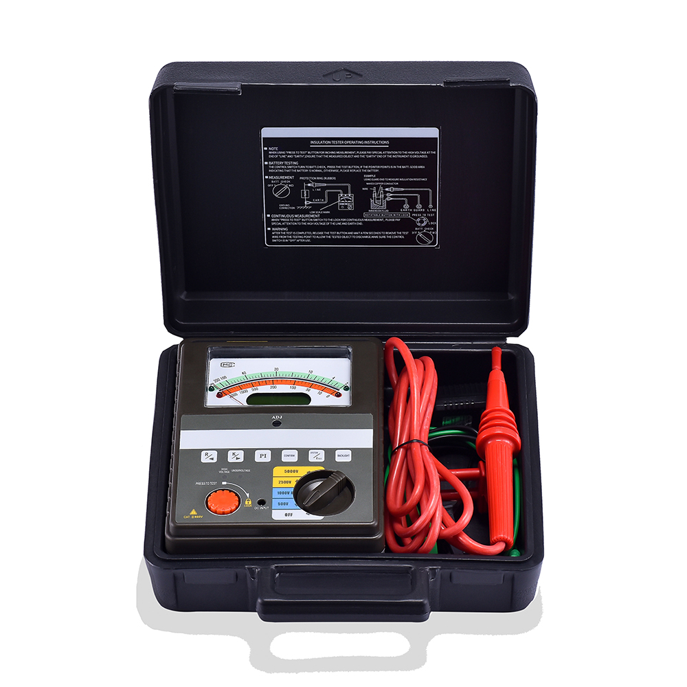
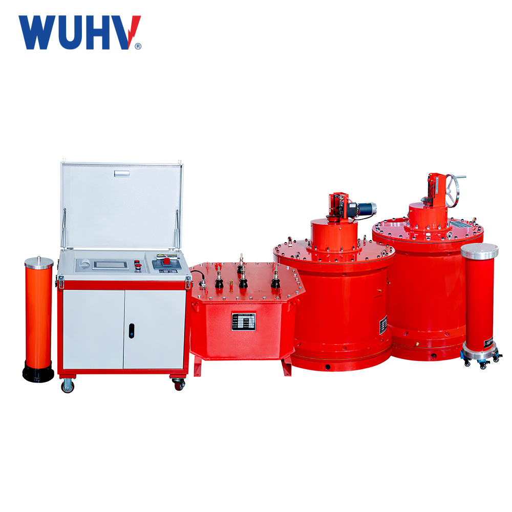
The insulation resistance tester초고압 전력을 사용하면 많은 전력 작업자가 다양한 전력 테스트를 더욱 편리하게 수행할 수 있습니다.

The insulation resistance tester has three types of tests for measuring insulation resistance. Each test uses its own method, focusing on the specific insulation characteristics of the tested equipment. Users need to choose the most suitable one for testing requirements.
Point test: This test is suitable for devices with minimal or negligible capacitance impact, such as short circuits.
The test voltage is applied over a short distance of time until a stable reading is reached, and the test voltage can be applied for a fixed period of time (usually 60 seconds or less). Collect readings at the end of the test. Regarding historical materials, we will draw maps based on the reading of historical materials. The observation of trends is conducted over a period of time, usually several years or months.
This test is usually used for testing or historical records. Changes in temperature and humidity may affect readings, and compensation must be made if necessary.
Durability testing: This test is applicable for guessing and preventive protection of rotating machinery.
Read continuously at specific times (usually every few minutes) and compare the differences in readings. Excellent insulation will display a continuous increase in resistance value. If the reading stagnates and does not increase as expected, the insulation may be weak and may require attention. Damp and contaminated insulators may lower resistance readings as they increase leakage current during testing. As long as there is no significant temperature change in the tested equipment, the impact of temperature on the tested equipment can be ignored.
Polarization index (PI) and dielectric absorption ratio (DAR) are commonly used to quantify the results of endurance testing.
Polarization Index (PI)
The polarization index is defined as the ratio of the resistance value within 10 minutes to the resistance value within 1 minute. It is recommended to set the minimum PI value of AC/DC rotating machinery at B, F, and H temperature levels to 2.0, and the minimum PI value of Class A equipment should be set to 2.0.
Attention: Some new insulation systems have faster response times to insulation testing. They usually start from test results within the G Ω range, with a PI between 1 and 2. In these cases, PI calculation can be ignored. If the insulation resistance exceeds 5G Ω within 1 minute, the calculated PI may be meaningless.
Step voltage test: This test is particularly useful when the additional voltage of the equipment is higher than the available test voltage generated by the insulation resistance tester.
Gradually apply different voltage levels to the tested device. The recommended test voltage ratio is 1:5. The testing time for each step is the same, usually 60 seconds, from low to high. This test is generally used at a test voltage lower than the additional voltage of the equipment. The rapid increase in test voltage level can cause additional pressure on insulation and render defects ineffective, resulting in lower resistance values.
Test voltage selection
Due to the high DC voltage used in insulation resistance testing, it is necessary to select an appropriate testing voltage to prevent excessive stress from being applied to the insulation, which may lead to insulation failure. The test voltage may also vary according to international standards.


