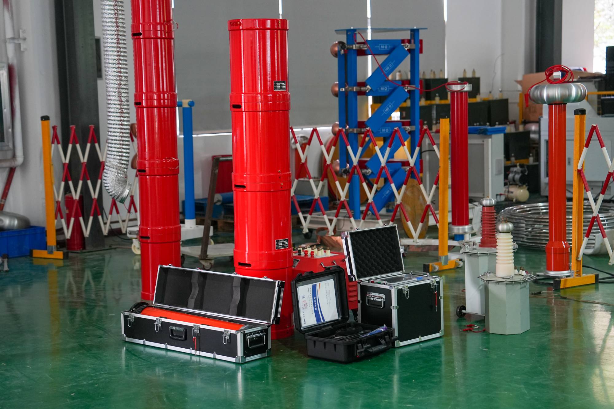
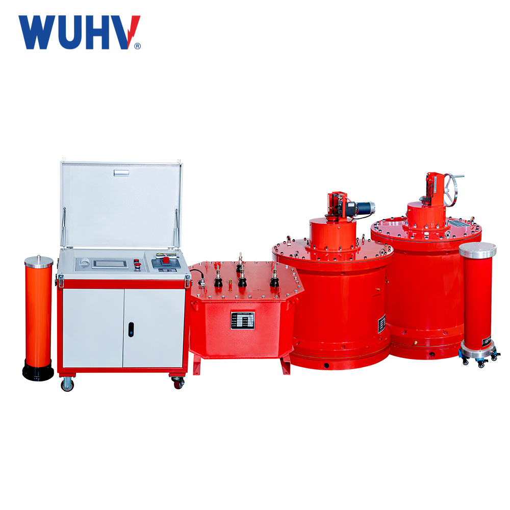
Principle of series resonance withstand voltage test? Wuhan UHV specializes in the production of series resonance, with a wide range of product selection and professional electrical testing. To find series resonance, choose Wuhan UHV.
The main uses and advantages of series variable frequency resonance
main purpose
The frequency conversion resonance test method, as one of the best equivalent methods for power frequency withstand voltage testing, is mainly used for on-site AC withstand voltage testing of capacitive power equipment with large capacitance values, including cross-linked polyethylene medium low voltage/high voltage/ultra-high voltage power cables (XLPE), fully enclosed high voltage combination devices (GIS), generator stators, large transformers, overhead power lines, power capacitors, etc.
superiority
The handover or preventive testing of the above power equipment requires a power frequency withstand voltage test, but due to the large capacitance of the test sample, the testing equipment has a huge power and volume, making on-site testing very difficult. The alternative inductive power frequency parallel resonance test device, due to its bulky and complex equipment, was previously mainly used for voltage withstand testing of generator stators. The direct current high voltage test on cables has also been prohibited or not recommended by regulatory authorities with the popularity of XLPE cables. Replacing it with a lightweight and simple series variable frequency resonance method for AC withstand voltage testing of capacitive specimens has become a popular trend and quickly accepted by various industries.
Of course, all of this is due to the rapid development of microcontroller technology and high-power power electronics technology, otherwise it would not be technically feasible.
The AC method should be used for the pressure test of the groove. Here is an overview of several common methods:
① Power frequency method: Due to the large power and volume of the required equipment, on-site implementation is very difficult.
② 0.1Hz test: Except for Paul's company, which ensures that true sine waves are suitable for use, most of the domestically produced ones are square waves and quasi sine waves, which have severe waveform distortion and poor test results.
③ Parallel resonance method using resonant transformers: Due to the low Q value and complex mechanical mechanism, the testing equipment is still relatively large and complex, but it is currently the most widely used practical method.
④ Variable frequency series resonance method: With the popularization of power electronics technology and computer technology, the Q value can be greater than 30, the equipment is simple, and the on-site use is convenient. It is currently the best AC withstand voltage test method equivalent to power frequency.
Troubleshooting methods for on-site testing
Due to the fact that all on-site tests are high-voltage destructive tests, it is necessary to have a certain understanding of the testing equipment and samples during use, and the on-site wiring operation must be correct and error free. In addition to carefully reading the instruction manual, the summary of experience based on various on-site operation tests is as follows:
Before the experiment, understand the condition of the test sample, including estimated capacitance, voltage level, frequency range, and then calculate the high voltage current and power consumption. And check the following items:
a, The power capacity of the host and excitation transformer shall not be less than the calculated power consumption.
b, Select different output terminals of the excitation transformer based on two parameters.
(a) According to the calculation, the high voltage current should not exceed the nominal current at the output terminal.
(b) According to the Q value, check if the output terminal is suitable. Generally, the cable should be set high (above 40), and the generator and GIS should be set low (below 25)
c, The combination of reactors meets the requirements of withstand voltage and high voltage current.
(a) Each individual reactor can withstand a voltage of 22kV, and the stacked reactor can withstand a voltage of 11kV
(b) When no radiator is added, the 3H reactor is 3A, 13H is 1.2A, and 75H is 0.8A. When a radiator is added, the 3H reactor is 5A, 13H is 2.5A, and 75H is 1.2A.


