The series RLC circuit consists of a resistor R, an inductor L, and a capacitor C connected in series. As in an ideal series LC circuit without resistance, oscillation with resonant frequency may occur in an RLC circuit, but due to the presence of resistance, this resonant frequency will attenuate.
Series resonance (also known as variable frequency resonance) occurs at the frequency with the minimum impedance of the circuit, where the reactance of the circuit is zero. In other words, if the impedance is only resistive without reactance, i.e. its imaginary part is zero, this situation will occur. When the reactance of an inductor and a capacitor is equal, resonance occurs, and due to their opposite signs, they cancel each other out. The following vector diagram shows this situation.
The calculator also calculates the Q factor of the serial RLC circuit - a parameter used for series resonant circuits and devices, as well as mechanical resonators. The higher the circuit resistance, the greater the loss and attenuation of the RLC circuit, and the lower its quality factor. Calculate the Q factor of the sequential RLC chain using the above formula.

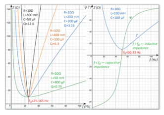
The graph shows the relationship between impedance Z and frequency f of the RLC in a serial RLC circuit under given resistance, inductance, and capacitance values. It can be seen that during resonance, the impedance is resistive rather than reactive. As the frequency increases, the reactance of the inductor increases and the reactance of the capacitor decreases. If the frequency decreases to zero (i.e. the source generates a constant voltage), the reactance of the inductor decreases to zero and the capacitor becomes infinitely large. That is to say, at zero frequency (DC), a serial RLC circuit is only an open circuit with infinite impedance. The right figure shows the frequency impedance and phase difference of a series resonant RLC circuit. On the right side of resonance, impedance is inductive, while on the left side it is capacitive.


