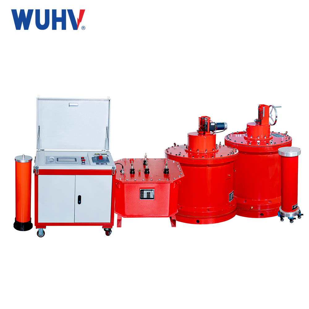
Series resonant (also known as variable frequency resonant) circuit is a circuit composed of inductors and capacitors connected in series.
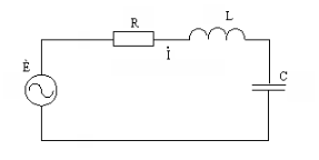
R is the equivalent ("virtual") active resistance of a circuit, representing the loss of reactive elements. Moreover, L and C themselves can be expressed as ideal without loss.
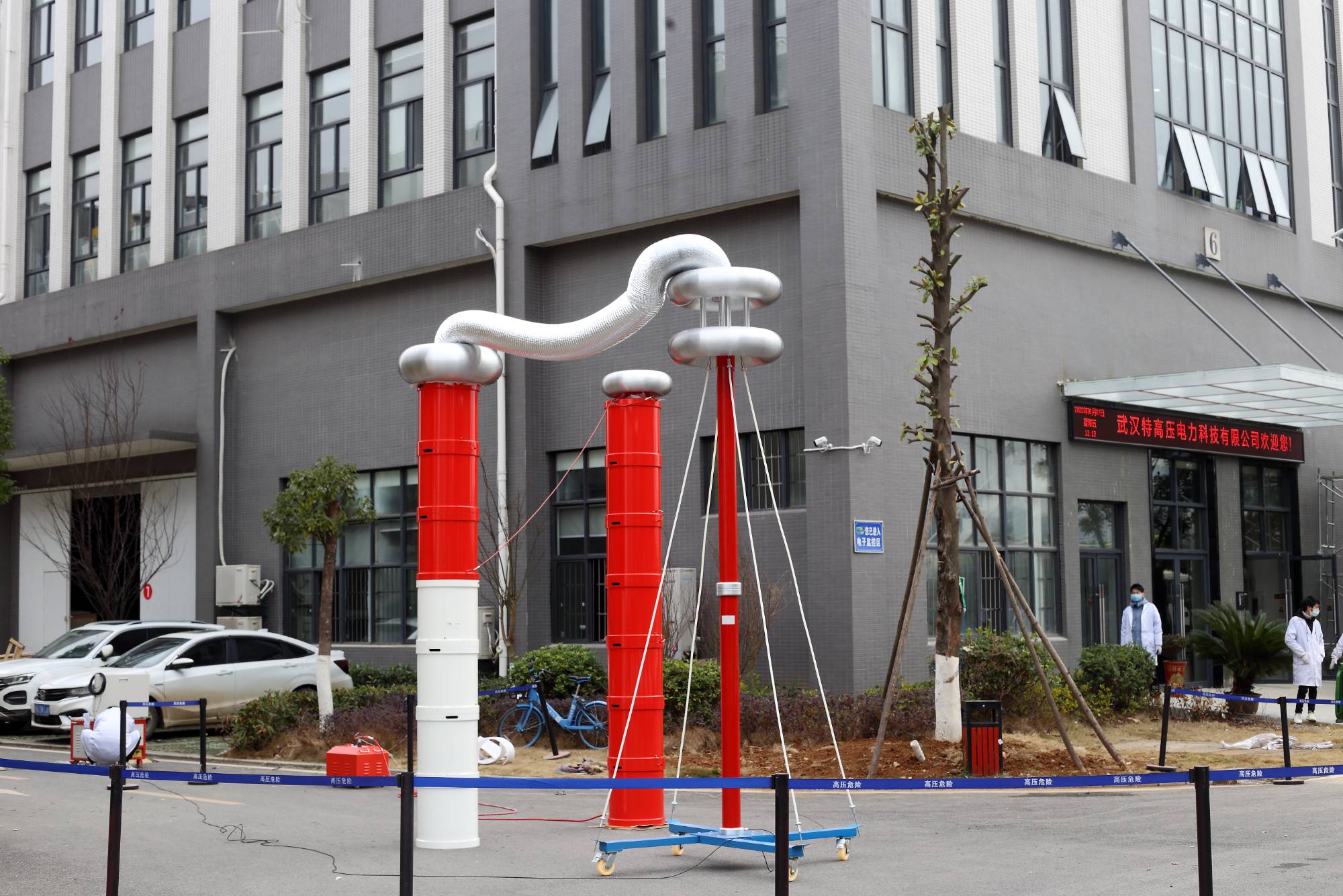
Circular frequency: ω=2 πƒ. So the current in the circuit is α=È/Zn, where Zn is the total complex resistance of the circuit. As you know, for a series resonant circuit, it is defined as the sum of the resistances of all its elements

It can be approximated that the active component of the input impedance R is independent of the frequency of the generator, although this is not entirely true in reality. Here, the skin effect factor plays a role, the proximity effect plays a role, and the quality factor depends on other effects. However, to understand how the reactance of a circuit varies with frequency, these subtle details can be ignored so far. The reactance component is a function of frequency and depends on the magnitude of L, C, and ω, which may vary in magnitude and sign.
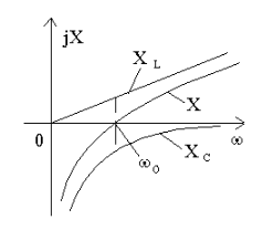
At point ω 0, the circuit enters a state where
X C =-X L,X = 0。 This mode is called series resonance, ω 0 L - 1 /ω 0 C = 0, From there, ω 0=1/√ LC or ƒ 0=1/(2 π√ LC),
The formula for the resonant frequency of a circuit was first derived by the great British physicist Sir William Thomson (1824-1907) and renamed Lord Kelvin after his absolute temperature scale.
At the resonance point Ζ=R, the current in the circuit is I 0=E/R, and the voltage of the capacitor and inductor is equal and opposite in sign
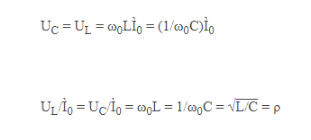
ρ - Characteristics or wave impedance of a circuit.
Obviously, ρ>R, therefore U C=U L>E, its name comes from series resonance. Those. The voltage amplitude of the reactive element at the resonant frequency is tens or hundreds of times higher than that of the power supply. Similar phenomena have also been observed in mechanics, such as pendulum, swing amplitude, and resonance phenomenon, which is a common name.
The characteristic of this increase in amplitude lies in the following relationship

Q is a dimensionless quantity called the quality factor of a circuit.
We note the expression Q=ρ/R=√ L/C/R, from which we can conclude that as the L/C ratio increases, the quality factor should increase. However, this is not the case. The fact is that as L increases, R also increases simultaneously, because the number of turns and coil size increase, and roughly speaking, the length of the coil wire and its ohmic resistance also increase. Therefore, the dependence of the quality factor of a circuit on the ratio of inductance to capacitance is more complex and cannot be described by a simple formula.


