



Product Introduction
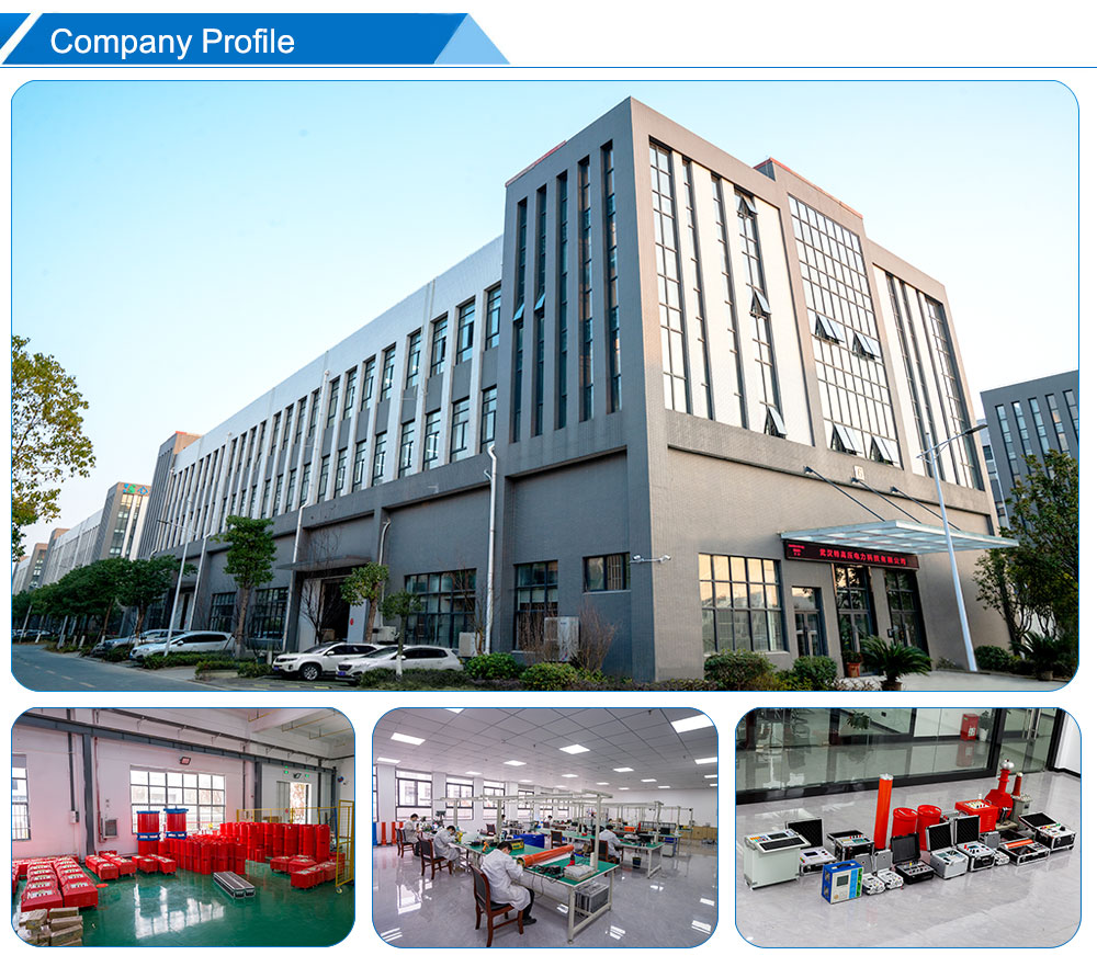
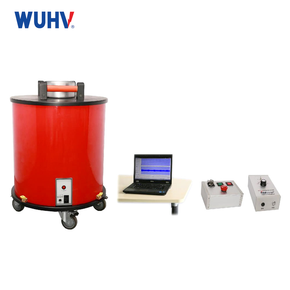
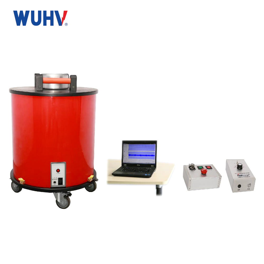
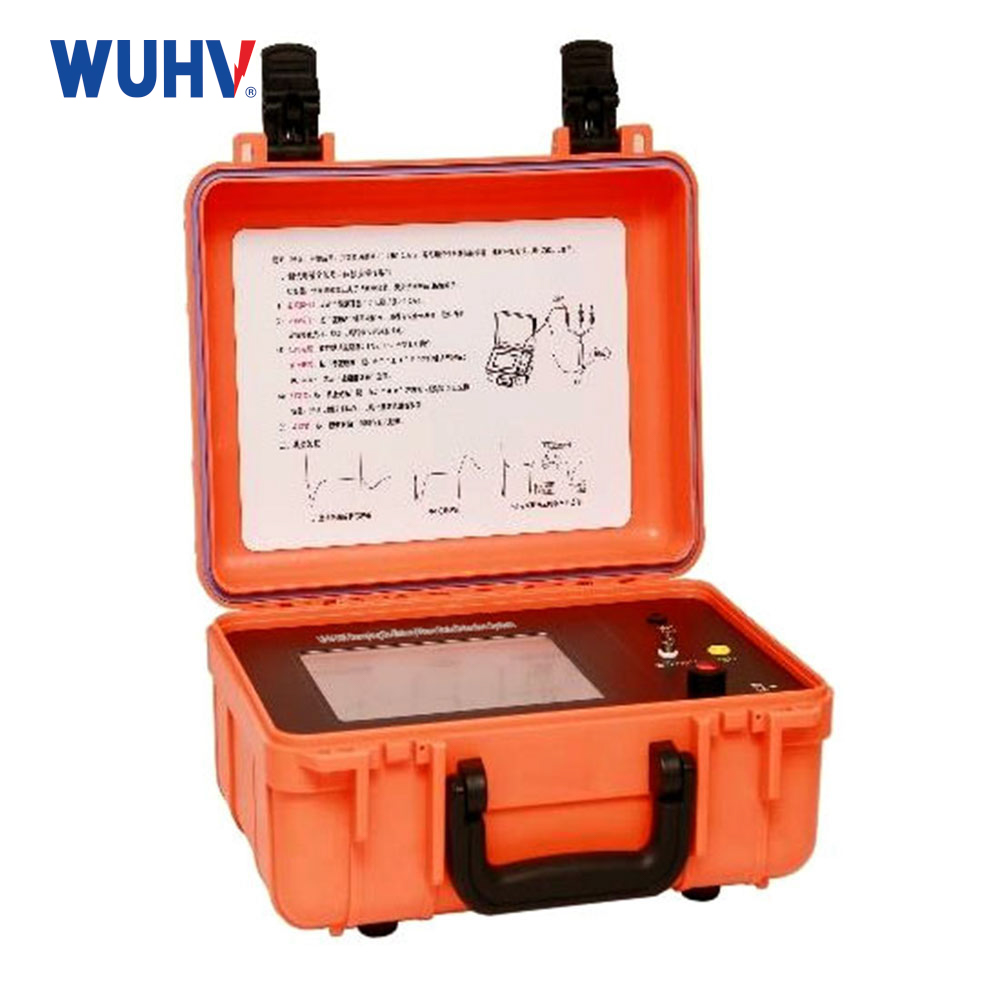
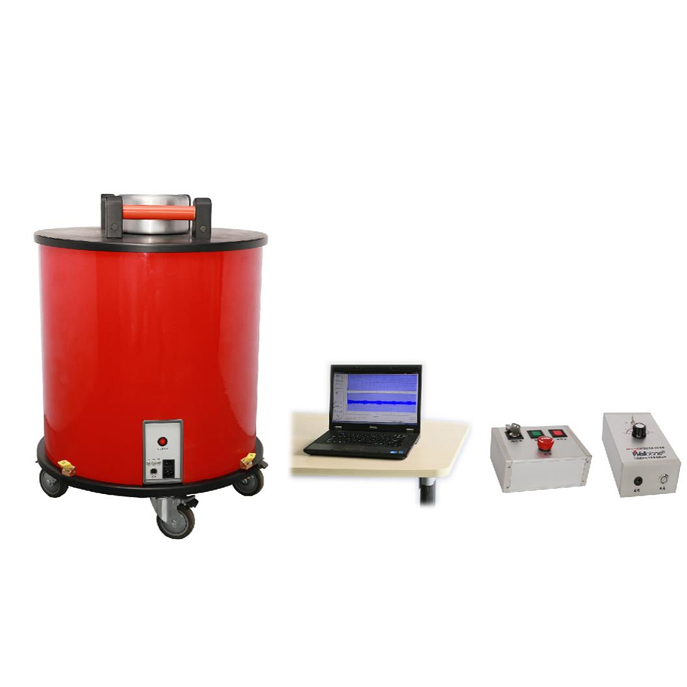
Wuhan UHV Power Technology Co.,Ltd., is a professional manufacturer and supplier of high-voltage power testing equipment in China.The UHV-505 Damped Oscillation Wave Detection System is a portable, all-in-one solution for on-site cable diagnostics. It performs non-destructive testing using Damped AC Voltage (DAC) up to 30kV, combining partial discharge detection and dielectric loss measurement to assess insulation defects and aging. Featuring advanced hardware/software integration, it supports cloud data upload for remote analysis, enabling efficient field condition assessment and predictive maintenance.
Product functions
Damped oscillating wave testing
Automatic voltage boosting
Automatically generates damped oscillating wave voltage
Supports oscillation frequencies from 20 Hz to 500 Hz
Maximum output voltage peak: 30 kV
Partial discharge detection
Detects partial discharge in cable insulation
Partial discharge measurement range: 1 pC to 100 nC
Complies with IEC 60270 standard requirements
Supports real-time high-speed partial discharge sampling
Partial discharge location
Locates partial discharge defects
Supports on-site amplification and analysis of partial discharge waveforms
Assists in determining the source location of partial discharge
Positioning accuracy up to 1% of cable length, with a minimum resolution of 2 m
Dielectric loss measurement
Measures dielectric loss of cable insulation
Measurement range: 0.1% to 10%
Used to assist in evaluating cable insulation condition and aging level
Partial discharge automatic / manual calibration
Supports automatic calibration
Supports manual calibration
Improves the accuracy of partial discharge test data
High-speed digital signal acquisition and processing
Uses high-speed digital signal processing technology
Supports digital filtering
Partial discharge real-time sampling rate up to 100 MHz
Supports test waveform data storage
제품 특징
1、State-of-the-art semiconductor technology
2、Cutting-edge laser control systems
3、High-performance digital signal processing with advanced filtering
4、Intelligent wireless network control
5、Cloud-based data management for remote analysis and reporting
제품 매개변수
Main technical index
| Item | Technical index |
| 전원공급장치 | 220VAC±10%, 50Hz |
| Maximum output voltage (peak) | 30kV |
| Oscillation frequency range | 20Hz ~ 500Hz |
| Test cable length range | 200m ~ 20km |
| High voltage charging current | 8mA |
| High voltage switch | Trigger mode: Laser triggers high voltage switch |
| High voltage switch characteristic | Conduction time: 1μs |
| Switching resistance: less than 1Ω | |
| Optical fiber communication | |
| Measuring range of local discharge | 1pC ~ 100nC |
| Local discharge level detection and bandwidth | In line with the International Electrotechnical Commission IEC60270 standard |
| Office release location bandwidth | 150kHz ~ 45MHz automatic adjustment |
| Local discharge positioning measurement accuracy | Cable length 1% (minimum resolution 2m) |
| Dielectric loss measurement range | 0.1% ~ 10% |
| Real-time sampling rate of office release | 100MHz |
| Local sampling storage depth | 32MB (can record 300ms data length) |
| Control mode | Wireless control, wired control |
| Local discharge calibration mode | Automatic/manual |
| Damping oscillatory wave realization | Automatic voltage boost, automatic generation of damped oscillation wave voltage |
Main functions of system software
| Software information recording interface | (1) | Record the time and date |
| (2) | Basic information of registered users: test personnel | |
| (3) | Basic information of the test cable: including the name of the test cable station, cable model, length, joint, operation history, etc | |
| Software main function | (1) | All Chinese operation interface |
| (2) | Support one-key compression, automatic calibration, one-key analysis | |
| (3) | Convenient and intuitive setting of voltage amplitude, control automatic boost and oscillation wave generation | |
| (4) | Multi-terminal WEB browsing cloud test data function (network support required) | |
| (5) | Automatic synchronization of basic data parameters (network support required) | |
| (6) | Automatic display of oscillating wave voltage amplitude, oscillation frequency and sampling time width | |
| (7) | Automatic display of dielectric loss value | |
| (8) | Automatic display of maximum volume | |
| (9) | Store oscillating waveform and local release waveform | |
| (10) | The local release waveform can be amplified on site for initial positioning of the local release source point | |
| (11) | Automatic or manual analysis of detection data automatically generate office release location map, automatically generate statistical reports | |
| (12) | Automatic generation of office release statistical maps, such as Q-φ chart, N-φ chart, etc |
Application Scenarios
Pre-commissioning testing of power cables
Insulation condition testing of newly laid cables before commissioning
Checking whether there are potential insulation defects in the cable body and cable joints
Providing condition assessment basis for cable commissioning
Preventive testing of cables
Regular testing of in-service power cables
Evaluating cable insulation condition through damped oscillating wave, partial discharge, and dielectric loss data
Identifying potential insulation defects in advance to reduce the risk of sudden failures
Condition assessment of in-service cables
Evaluating the insulation health condition of long-term in-service cables
Comparing test data from different time periods to analyze trends in insulation condition changes
Providing data basis for cable maintenance and replacement
Partial discharge detection in cables
Detecting potential partial discharge within cable insulation
Determining whether there are weak insulation points in the cable
Performing waveform and phase-resolved pattern analysis of partial discharge signals
Partial discharge fault location in cables
Determining the location of detected partial discharge defects
Quickly narrowing the scope of fault investigation
Assisting on-site maintenance personnel in locating cable defect positions
Cable joint condition testing
Testing key areas such as cable intermediate joints and terminations
Identifying potential issues such as poor joint workmanship and insulation defects
Particularly suitable for lines with a large number of cable joints
Post-maintenance cable acceptance
Condition testing after cable repair, replacement, or joint handling
Verifying insulation performance after maintenance
Confirming whether the cable meets the conditions for re-commissioning
FAQ about Damping Oscillatory Wave State Detection System
Q: What is the difference between the UHV-505 and ordinary withstand voltage test equipment?
A: The UHV-505 not only performs voltage testing, but also integrates partial discharge detection, partial discharge location, and dielectric loss measurement functions, with a greater focus on cable insulation condition diagnosis. When making a purchasing decision, selection can be based on whether the project primarily requires withstand voltage testing, or if it focuses more on insulation condition assessment and defect diagnosis.
Q: In addition to partial discharge, what else can the UHV-505 detect?
A: In addition to partial discharge, the device also supports damped oscillating wave testing and dielectric loss measurement. The dielectric loss measurement range is 0.1% to 10%, enabling comprehensive evaluation of cable insulation condition by combining multiple test data sets.
Q: Who is the damped oscillating wave detection system suitable for?
A: It is mainly suitable for power utilities, power plants, substations, power testing institutions, cable manufacturers, rail transit power supply systems, and large industrial enterprises that need to perform power cable testing and condition assessment. For organizations that need to conduct a large number of on-site cable tests, the integrated testing and data management functions also help improve testing efficiency.
Q: How can one determine whether a system is suitable for their project when making a purchase?
A: It is recommended to provide information such as the rated voltage, type, length, quantity, joint conditions, testing purpose, and on-site power supply conditions of the cables to be tested before purchase. The supplier can then verify the test voltage, detection range, and equipment configuration based on the actual operating conditions. For large cable testing projects, on-site space, safety clearance, grounding conditions, data management requirements, and after-sales technical support should also be confirmed in advance.