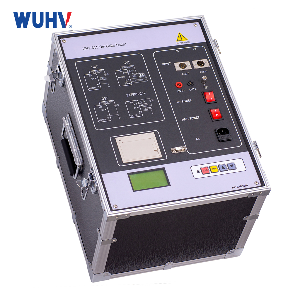
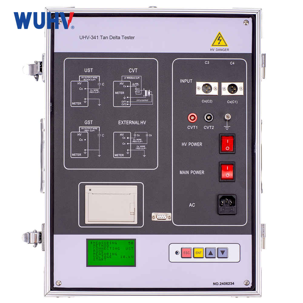


Introduction
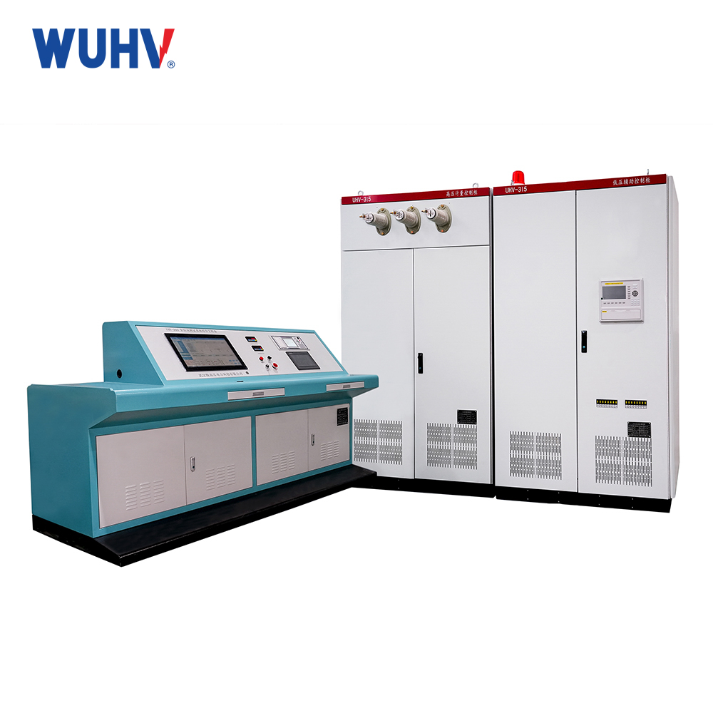
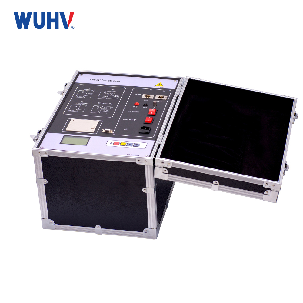
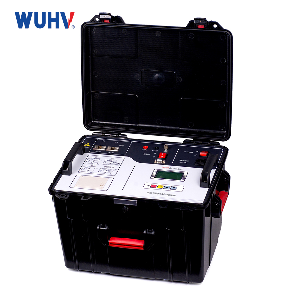
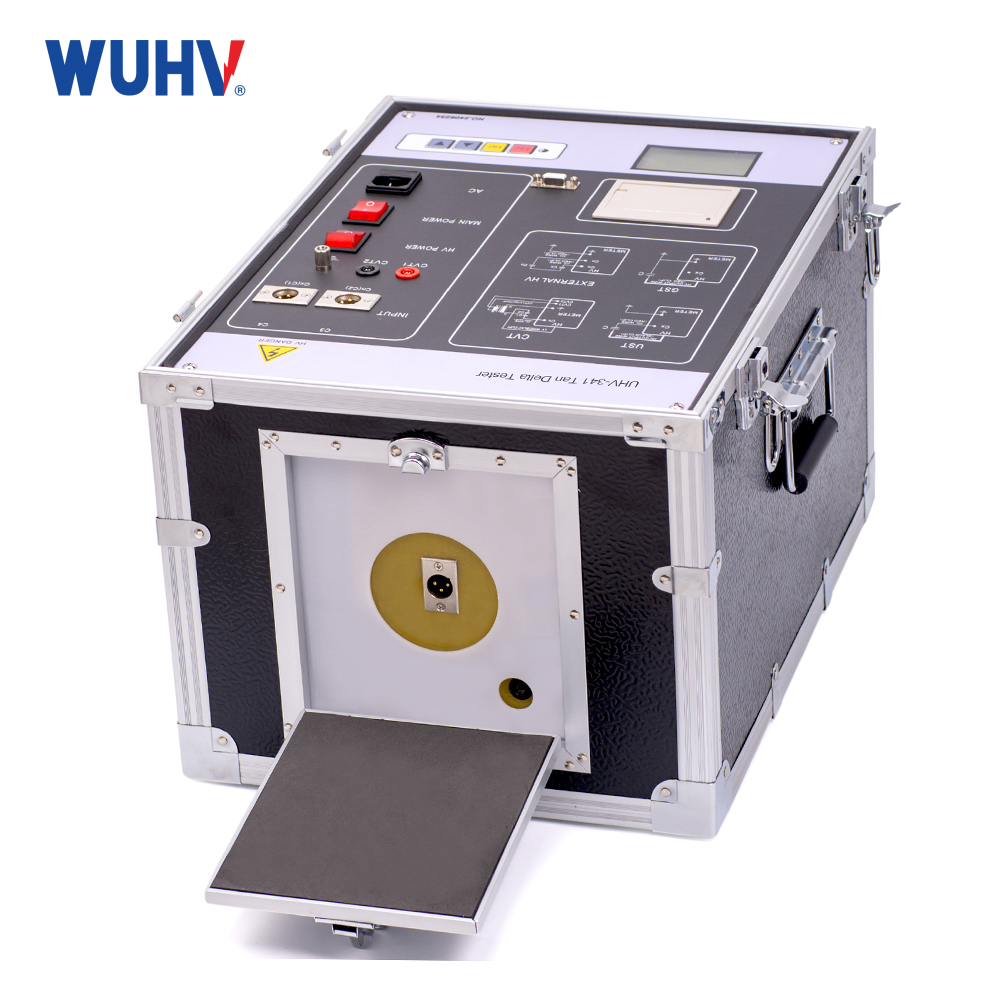
Transformer Tan Delta Tester is a kind of instrument with high precision fully automatic measuring the dielectric loss tangent and capacitance of various high voltage electrical equipments in the power plants and substations. The adoption of frequency conversion technology could ensure the accurate measurement in the interference of strong electric field.
기술적인 매개변수
| 고전압 출력 | 0.5~10kV |
| 각 레벨마다 500V씩 증가, 총 20레벨, 용량: 1500VA | |
| 정확성 | tgδ: ± (reading * 1.5% + 0.06%) |
| Cx: ± (reading * 1.5% + 5PF) | |
| 해결 | tgδ: 0.001% |
| Cx: 0.001pF | |
| 측정 범위 | 0.001% |
| Internal high pressure | 3PF~<60000PF/10KV |
| 60PF~1uF/0.5KV | |
| External high pressure | 3PF~1.5uF/10KV |
| 60PF~30uF/0.5KV | |
| 전원공급장치 | AC 220V ± 10% 50/60 ± 1Hz |
| 측정 방법 | a.single frequency: 45(45Hz measuring)、50(50Hz measuring)、55(55Hz measuring)、60(60Hz measuring)、65(65Hz measuring) |
| b.different frequency: 50D(45Hz/55Hz measure each time) 60D(55Hz/65Hz measure each time) Automatic frequency conversion | |
| 고조파 적응 | ≤3% |
| 신청조건 | -15℃-50℃ Relative humidity<80% |
| 치수 | 460 (L) × 345 (W) × 345 (H) |
| 무게 | 35kg |
 |  |  |
Product Characteristics
1、The adoption of frequency conversion technology could ensure the accurate measurement in the interference of strong electric field.
2、The whole process is measured automatically through microcomputer.
3、It could measure non-grounded or grounded high voltage equipments adopting positive and negative connection method. Besides, it could measure the tgδ of capacitor voltage transformer and capacitance of main capacitor C1and C2.
4、Under the circumstance of oil dielectric loss ≥ 0.01%, with oil cup, positive wiring can be used to measure the dielectric loss of oil.
5、The instrument has the advantages of convenient and safe operation.
6、it takes security measures like zero-cross closing, lightning protection, etc.
Technical Advantages
1. Intelligent control system: Adopting fully digital SPWM frequency conversion control technology and a 16 bit high-precision frequency conversion regulation system, it realizes automatic identification of resonance points and improves boost efficiency by more than 40% compared to traditional equipment. The high and low voltage closed-loop negative feedback circuit ensures that the voltage extreme value error is always controlled at a high-precision level of ≤ 3% within the dual frequency band adjustment range.
2. Modular design: The reactor supports modular combination, with a volume reduction of 35%, making it easy to transport and assemble on site, especially suitable for complex operating environments such as outdoor and mountainous areas. The high-voltage output protection resistor is integrated into the boost body, simplifying the operation process and shortening the overvoltage protection response time to within 20 milliseconds.
3. Anti interference capability: Using frequency conversion technology and digital filtering algorithms, the measurement accuracy can still be maintained in strong electric field interference environments, the signal-to-noise ratio is increased by 300%, and the false alarm rate is less than 0.1%. Support generator power supply detection scenarios and adapt to various complex testing environments.
4. Safety protection system: equipped with a seven fold safety interlock mechanism, including functions such as closed-loop feedback of charging voltage and automatic discharge. The current, voltage, and waveform data are all directly sampled from the high-voltage side, and the data is true and accurate, avoiding distortion during signal transmission.
 |  |  |
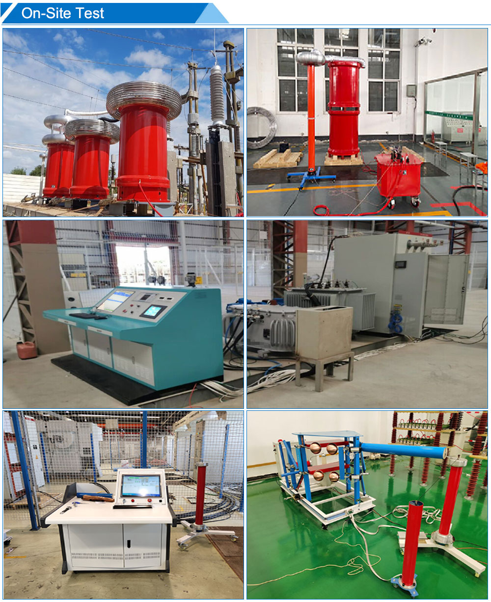
1. Handover test: Before the new equipment is put into operation, insulation performance testing shall be conducted on high-voltage equipment such as transformers, transformers, bushings, circuit breakers, capacitors, etc., and the equipment quality shall be accepted to ensure compliance with the commissioning standards.
2. Preventive maintenance: Regularly measure the dielectric loss and capacitance of high-voltage power equipment in operation, detect the moisture, aging, and local defects of insulation materials, predict equipment failures in advance, avoid insulation breakdown and other safety accidents, and ensure the stable operation of the power system.
3. Fault diagnosis: When insulation abnormalities occur in power equipment, accurate measurement of tg δ and Cx values is used to analyze the cause of the fault (such as moisture, aging, partial discharge, etc.), providing scientific basis for equipment maintenance.
4. Research and Teaching: Provide a standard testing platform for power research institutions and universities, supporting research on insulation material properties, optimization of testing methods, and related professional teaching experiments.
5. Insulation oil testing: equipped with standard oil cups and dedicated testing lines, it can measure the loss of liquid insulation media such as transformer oil and evaluate the insulation performance of insulation oil.
Frequently Asked Questions (FAQ)
1. Why do we need to do dielectric loss testing?
The main purpose is to evaluate the health status of insulation materials, promptly identify potential insulation degradation issues, and prevent power safety accidents.
2. Is it better if the tan δ value is higher or lower?
The lower the tan δ value, the smaller the dielectric loss of the insulation material and the better the insulation performance.
3. Why is "variable frequency" needed during testing?
Dielectric loss characteristics of insulating materials vary at different frequencies. Variable-frequency testing can more comprehensively reflect the true state of the insulation and help distinguish different types of defects.
4. What should I do if the test finds that the loss value is too high?
It is necessary to combine other detection methods and have professional engineers conduct comprehensive analysis to develop corresponding treatment plans, such as drying and replacing insulation parts.
5. What impact does testing in a humid environment have on the results?
High humidity can increase insulation surface leakage, leading to an increase in tan δ value and affecting the accuracy of testing. Therefore, certain protective measures need to be taken when testing in humid environments.
6. What are our advantages in this field?
We have advanced high-voltage testing instruments, a professional electrical equipment testing team, and rich experience in power equipment operation and maintenance, committed to providing customers with high-quality insulation withstand voltage testing services.